Representations of Position, Orientation and Motion
Disclaimer! Notes are currently still in progress.
Table of Contents:
Introduction
The heart of robotics is motion. (Matt Mason)
Robotics involves perceiving, predicting, creating and controlling motion. Motion is the change in position over time. Thus, we need to be able to represent the position and orientation of a rigid body in 3D space to be able to do these things.
Notation and Conventions
In this course, we’ll use the following notation:
- $A \in \mathcal{R}^{m \times n}$: a capital letter will denote a matrix with m rows and n columns. The entries of $A$ will be real-valued.
- $x \in \mathcal{R}^{n}$: a small letter will denote a vector with n entries.
- $\hat{x}$: vectors with a hat will denote unit vectors, i.e. vectors of length 1.
All vectors are to be considered column vectors, i.e.
If we want to explicitly denote row vectors, we will use the notation $x^T = [x_1, \dots, x_n]$.
Because we work with column vectors, multiplications involving rotation and general manipulation of these vectors will be represented as pre-multiplications, e.g. $y = Rx$.
We’ll also be using a right-hand coordinate system. That is the x, y, and z axes of our frames are aligned with the index finger, middle finger, and thumb of the right hand, respectively. Or mathematically, that $\widehat{x} \times \widehat{y} = +\widehat{z}$.
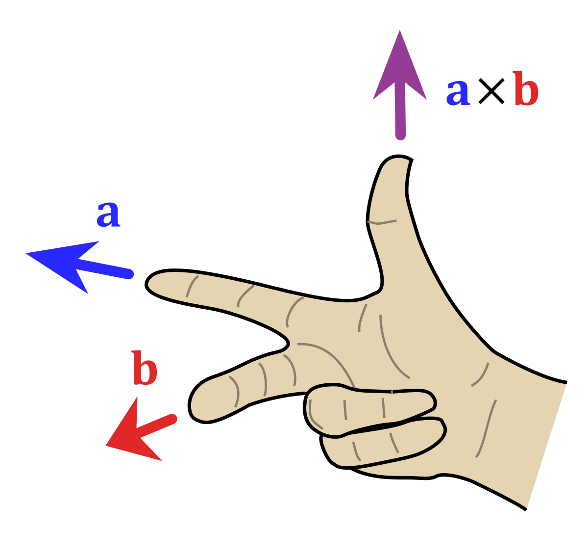
Positive rotation in a right-hand system is obtained using the “right-hand rule”: by aligning the thumb with the axis of rotation in the positive direction, the curl of the fingers represents a positive motion from the first axis to the second axis. In a right-hand coordinate system, this implies that a positive rotation about the z-axis when viewed from above is counter-clockwise.
Planar Rotations
Suppose we are given two coordinates frames: a stationary frame of reference $s$ and a body frame $b$. The coordinate frame $b$ is obtained by rotating the frame $s$ counterclockwise by $\theta$ about the origin. We would like to express the unit vectors of the rotated frame $b$ with respect to $s$.
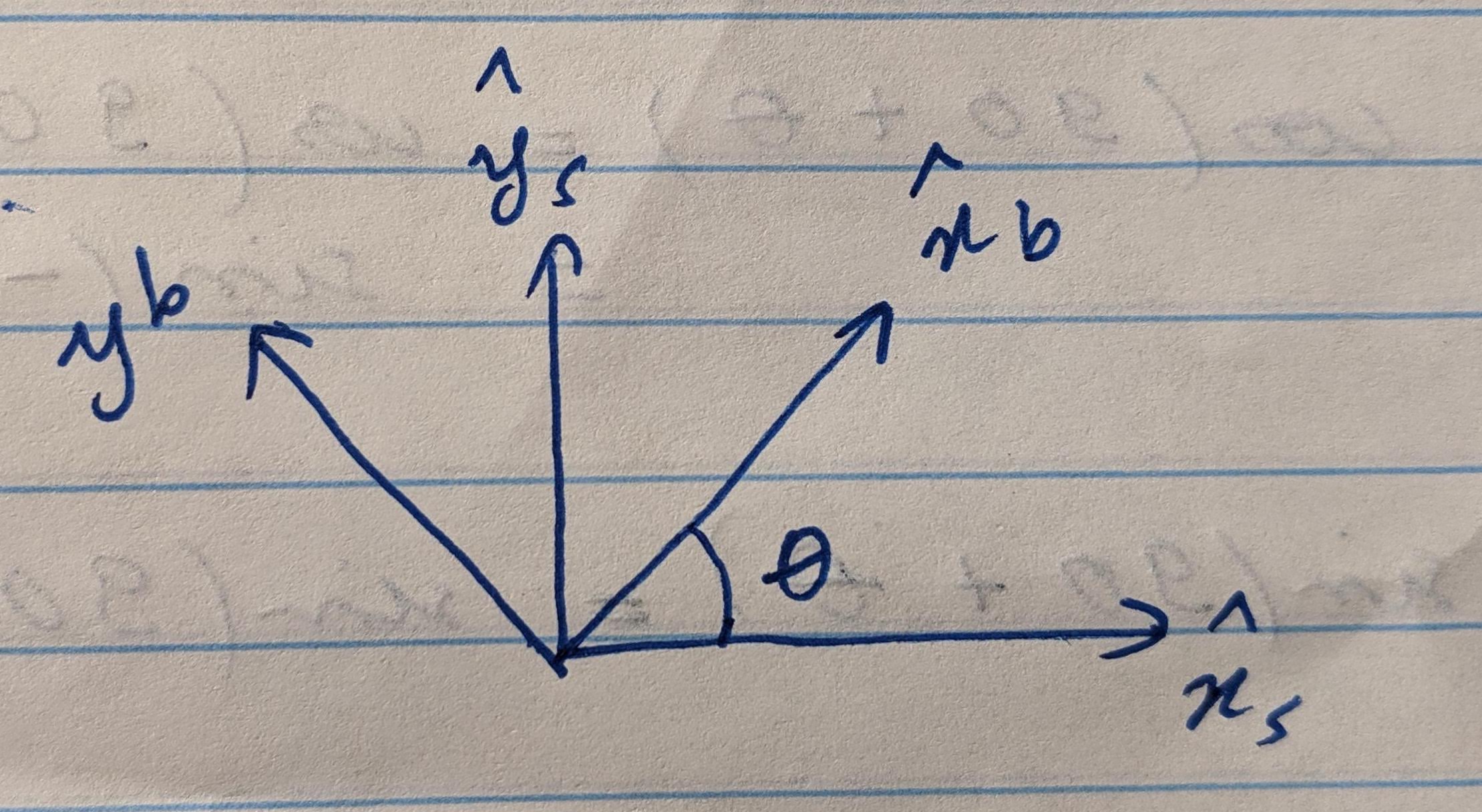
Because we are dealing with unit-vectors, the math will be equivalent to working in a unit-circle. In fact, $\widehat{x}_b$ will correspond to a rotation by $\theta$ in a unit-circle and $\widehat{y}_b$ to a rotation by $90+ \theta$. This allows us to write the following system of equations, based on the trig properties we derived in the previous section:
In matrix form:
Now consider any point $p$ in both frames. We can look at its coordinates with respect to $s$: $p = p_x \widehat{x}_s + p_y \widehat{y}_s$, or with respect to $b$: $p = p’_x \widehat{x}_b + p’_y \widehat{y}_b$. Again, in matrix form:
Thus, we have shown that
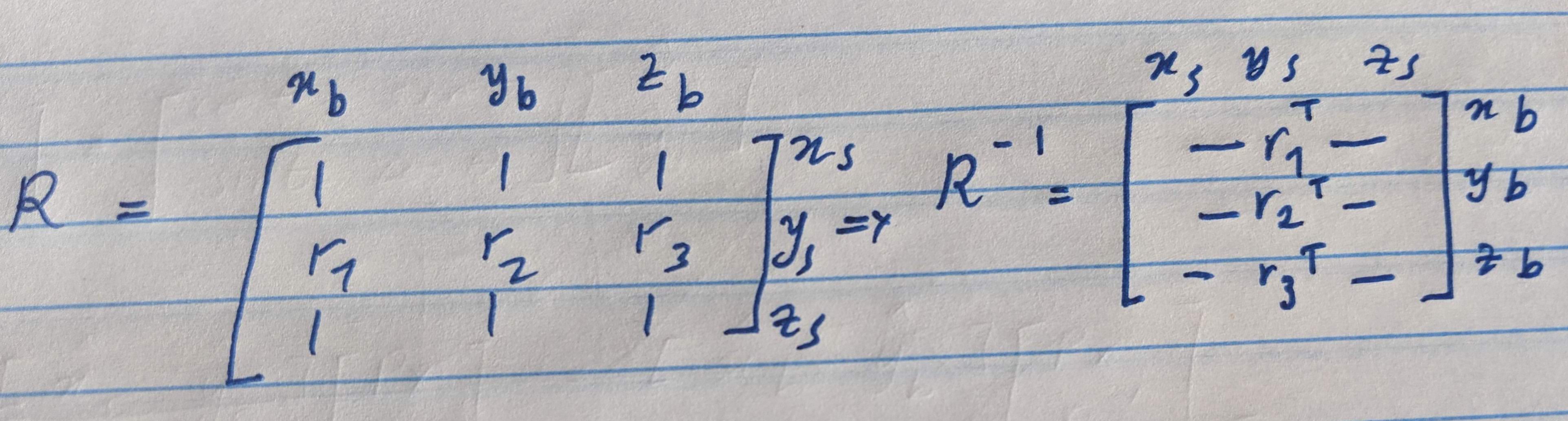
That is, if we have the coordinates of a point in a given frame $b$ and we know the orientation of $b$ with respect to a reference frame $s$, then we can create a rotation matrix $R = [\widehat{x}_b \ \widehat{y}_b]$, where the columns of R are the unit vectors of $b$ as seen in $s$. The matrix R represents a counter-clockwise rotation by an angle $\theta$.
Orientation in 3D
Talk about extending to 3D.
We can derive some very nice properties of this rotation matrix. First, since the columns represent the unit vectors in one system as seen by the other, simply taking the transpose will produce the inverse rotation.
Next, since the columns are unit vectors, then they are pairwise orthogonal. These two properties combine to define the rotation matrix as being orthogonal, $\ie R^T = R^{-1}$.